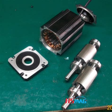
Permanent magnet rotor e1655961736623.jpeg.
Jun 23, 2022 · The rotor overtemperature caused by losses is one of the important issues for the high-speed electrical machine. This paper focuses on the rotor loss analysis and CFD-thermal coupling evaluation for 105 kW, 36,000 r/min HSPMSM. Three types of sleeve materials as carbon-fiber, Titanium alloy, and stainless steel are introduced in this paper, researching the effects of sleeve conductivity ...
The permanent magnet motor tends to have larger step angles, 7.5° or 15°, than the variable reluctance motor. The hybrid motor typically has 200 rotor teeth and rotates at 1.8° step angles. They have high static and dynamic torque and can run at very high step rates. As a consequence they are very widely used. Mar 20, 2021 · Reluctance is a function of rotor position in a variable reluctance motor. Sequential switching (Figure below) of the stator phases moves the rotor from one position to the next. The mangetic flux seeks the path of least reluctance, the magnetic analog of electric resistance. This is an over simplified rotor and waveforms to illustrate operation. Nov 12, 2020 · A double-sided permanent magnet rotor with a single stator [2, 3] can offset the axial attraction and increase the output power at the cost of an increased weight. The double-sided permanent magnet rotor design can also reduce bearing wear and noise problem compared with a single-sided structure, which thus increases the generator reliability. A dual-rotor permanent magnet Vernier machine (DRPMVM) with permanent magnets (PMs) on both sides of the rotor and stator is proposed and studied here. The configuration and working principle are provided, then the expression of coil-side voltage is obtained based on the rotating harmonics of the air gap flux density.Range of Surface-Mounted Permanent-Magnet. ... 413. [6] M. Hippner and R. G. Harley, 1992, “Looking for. an optimal rotor for high speed permanent magnet. synchronous machine”, Conference Rec ...
An internal permanent magnet synchronous machine (IPMSM) was designed for heavy-load traction vehicles applied in port transportation. Based on finite element analysis (FEA), the rotor iron core topology was optimized with the most attention paid to cogging torque and torque ripple. The influences of the iron core on the air-gap …
the permanent magnet Once the permanent magnet is inserted into a slot of the rotor core, it generates a stress-point within the core as a result of centrifugal force. If the permanent magnet slips out of the slot within the rotor core during operation of the drive motor as a result of this centrifugal force, the permanent magnet, the rotor core, or …The actual power capacity of permanent magnet synchronous machine for electric vehicles is usually limited by rotor temperature, ... Usually, measuring the temperature of the rotor permanent magnet is very difficult by equipping sensors to rotate the body directly. Some common techniques include slip rings, ...
A post-assembly magnetizing fixture has been designed and successfully used to magnetize the rotor of a 100 kW high speed permanent magnet synchronous motor. The rotor is a solid cylinder with outer diameter of 80 mm and total length of 515 mm. The permanent magnet material is samarium-cobalt (Sm 2 Co 17) withArnold produces high performance permanent magnet motor components and sub-assemblies for aerospace and defense, industrial, automotive, and motorsport applications, such as: KERS — Kinetic Energy Recovery System, which includes a composite sleeved RECOMA® SmCo magnet rotor for a 50,000+ RPM, 100KW+ system Brushless DC electric motor. The motor from a 3.5 in floppy disk drive. The coils, arranged radially, are made from copper wire coated with blue insulation. The rotor (upper right) has been removed and turned upside-down. The grey ring inside its cup is a permanent magnet. This particular motor is an outrunner, with the stator inside the rotor. Jul 1, 2017 · Unbalanced magnetic force (UMF) is one of the most important issues in permanent magnet (PM) machines with rotating asymmetric winding configurations, where the UMF is intrinsic [1, 2]. When these machines are perfectly manufactured, they show good electromagnetic performances such as high efficiency, high torque density, low torque ripple and ... Aiming at the rotor strength problem of high speed permanent magnet synchronous motor (HSPMSM), a design method for maximum outer diameter of permanent magnet is proposed. Firstly, on the basis of mechanics of materials, the stress analytical model of HSPMSM rotor with anisotropic material is established. Then, the …
Coaxial counter-rotating propellers have been widely applied in ships and helicopters for improving the propulsion efficiency and offsetting system reactive torques. Lately, the counter-rotating concept has been introduced into the wind turbine design. Distributed wind power generation systems often require a novel approach in generator …
The permanent magnet synchronous motor (PMSM) is widely used in the electric vehicle and domestic appliance industries. The structure of the PMSM motor varies depending on the permanent magnet arrangement in the rotor structure; among them, the interior permanent magnet (IPM) PMSM motors made by inserting permanent …
Electric machines with permanent magnet rotors are becoming increasingly popular due to the high power density that they offer relative to other configurations. Where the speed of rotation is high, the magnets are typically mounted on the surface of the rotor and retained by an outer sleeve. In the literature, a variety of analytical models have …2.2 External rotor permanent magnet motor rotor air gap magnetic field When the motor is running at no load, the air gap magnetic field is provided by the permanent magnet alone. The generated magnetic field rotates together with the rotor and the rotational speed is synchronous speed.Jan 24, 2021 · A permanent magnet rotor would be what you want in an application like this. Car alternators don’t use PM rotors bc they need to control rotor current in order to get relatively constant voltage ... Rotor configurations strongly affect the torque and efficiency performance of permanent magnet electric motors. In this paper, different rotor configurations of the permanent magnet BLDC motor ...1 INTRODUCTION. Due to the outstanding advantages of small size, high power density, low noise and high transmission efficiency, high-speed machine has been widely concerned [].Currently, there are mainly three types of high-speed machines: induction machine, switched reluctance machine and permanent magnet (PM) machine …Jul 1, 2017 · Unbalanced magnetic force (UMF) is one of the most important issues in permanent magnet (PM) machines with rotating asymmetric winding configurations, where the UMF is intrinsic [1, 2]. When these machines are perfectly manufactured, they show good electromagnetic performances such as high efficiency, high torque density, low torque ripple and ... Apr 1, 2023 · The rotor spinning at high speed generates a large tensile stress. Once the yield strength of the permanent magnet (PM) is exceeded, the permanent magnet will be broken. Therefore, a high-strength sleeve must be installed outside the permanent magnet [3, 4]. Many researchers have conducted extensive study on rotor strength analysis of HSPMSM ...
A high-speed (HS) permanent magnet (PM) synchronous motor (HSPMSM) with a carbon fiber-reinforced plastic (CFRP) protective sleeve in the surface-mounted rotor was explored in this study.Rotor configurations strongly affect the torque and efficiency performance of permanent magnet electric motors. In this paper, different rotor configurations of the permanent magnet BLDC motor ...Feb 9, 2018 · Electric machines with permanent magnet rotors are becoming increasingly popular due to the high power density that they offer relative to other configurations. Where the speed of rotation is high, the magnets are typically mounted on the surface of the rotor and retained by an outer sleeve. In the literature, a variety of analytical models have been proposed to aid the mechanical design ... Among them, the NS type rotor has a structure in which the permanent magnetization direction of the two-sided rotor is opposite. One rotor permanent magnet magnetic flux flow to the opposite rotor. The advantage is that there is no magnetic flux flowing through the Stator back-yoke, making the design easier. Furthermore, by …The most obvious performance difference is that a PMAC motor rotates at the same speed as the magnetic field produced by the stator windings, meaning it is a synchronous machine. If the field is “rotating” at 1800 rpm, the rotor turns at the same speed. An induction motor, on the other hand, is considered an asynchronous machine. For the high-frequency permanent magnet electrical machine, a reasonable mechanical aspect design is crucial to meet its stability and reliability. This study focuses on the accurate modelling and analysis of the natural frequencies and modes of the rotor assembly for a designed and manufactured 100 kW 32,000 r/min motor.Apr 1, 2012 · In fact, as weâ ll explore, the major difference between PMAC and permanent magnet DC motors is that the faster a PMACâ s rotor spins, the higher back-EMF voltage is generated.
In this work, different analytical methods for calculating the mechanical stresses in the rotors of permanent magnet machines are presented. The focus is on interior permanent magnet machines. First, an overview of eight different methods from the literature is given. Specific differences are pointed out, and a brief summary of the …1 Introduction. Flux-switching permanent-magnet (FSPM) motors have advantages such as high-power and -torque density, high efficiency and simple and robust mechanical structure in the rotor [1-4].These motors have bipolar flux linkage and sinusoidal back-electromotive force (EMF) [].In FSPM motors, because of the placement of …
Magnet Rotors. Magnetic rotor, or permanent magnet rotor is the non stationary part of a motor. The rotor is the moving part in an electric motor, generator and more. Magnetic rotors are designed with multiple poles. Each pole alternates in polarity (north & south). The windings of coreless axial flux permanent-magnet machine (CAFPM) are exposed to the rotor magnetic field, where each back electromotive force (EMF) harmonic is induced not only by several ...For permanent-magnet (PM) machines, only specific stator MMF harmonic, known as working harmonic, interacts with the PM field to produce continuous electromagnetic torque . Lower and higher order stator MMF spatial harmonics rotating at different speeds to the rotor, will bring about unwelcome effects, such as eddy current …A stationary magnetic field is produced across the rotor by poles on the stator. These poles may be encircled by field coils carrying direct current, or they may contain permanent magnets. The rotor or armature consists …Apr 8, 2022 · This paper proposes two structures of dual-stator permanent-magnet vernier machines (VMs) for high-torque low-speed applications. The proposed structures consist of dual-sided rotor which is sandwiched by inner and outer stators. These topologies include 22 and 46 consequent-pole magnets in the rotor and 24 and 48 stator slots for Design A and Design B, respectively. Design A is an improved ... Measure Skewing Angle. MagScope software makes it easier than ever to measure the skewing angle of skewed permanent magnet rotors, enabling the detection of skewing angle deviations. The right figure shows an example of the step skew on an IPM (Interior Permanent Magnet) rotor, represented in a cross-section graph with automatic zero-crossing ... Measure Skewing Angle. MagScope software makes it easier than ever to measure the skewing angle of skewed permanent magnet rotors, enabling the detection of skewing angle deviations. The right figure shows an example of the step skew on an IPM (Interior Permanent Magnet) rotor, represented in a cross-section graph with automatic zero …The rated power and speed of the permanent magnet grinding electric spindle are 7.5Kw and 950r/min, respectively.The main parameters of the PMGES are as follows, the rotor mass is m = 5.66 kg; the rotor radius is R = 0.072 mm; the axial length of the air gap is L = 0.178 mm, nominal air gap length is δ 0 = 3 × 10 −3 m, air permeability …
Rotor (electric) The rotor is a moving component of an electromagnetic system in the electric motor, electric generator, or alternator. Its rotation is due to the interaction between the windings and magnetic fields which produces a torque around the rotor's axis. [1]
Non−Magnetic Rotor Core Rotor Magnets Rotor Pole Pieces Figure 2: Axial View of a Flux Concentrating Motor The geometry of one type of internal magnet motor is shown (crudely) in Figure 2. The permanent magnets are oriented so that their magnetizationis azimuthal. They are located between wedges of magnetic material (the pole pieces) in …
Rotor position information is necessary for the control of a permanent magnet synchronous motor (PMSM) and position sensorless control is the trend for its low cost, high reliability and space-saving.A new technique for high performance and robust speed control of permanent magnet synchronous motor (PMSM) using a mixed non-linear H∞ and Sliding Mode Control (SMC) is applied.Aug 25, 2020 · Permanent Magnet AC Motors. Like an induction motor, a permanent magnet motor has a Stator configured to provide a number of poles, usually for a 3-Phase supply. However, instead of containing Rotor bars, the Rotor has magnets mounted on, or embedded in, the laminations. These magnets, which are often made from rare earth elements (neodymium or ... In this paper, an optimal design procedure which includes multi-physics analysis to design the multi-phase external rotor PMa-SynRMs is presented. In specific, a five-phase external rotor PMa-SynRM with neodymium based magnets has been proposed as a solution to produce higher power density compared to the conventional internal rotor PMa-SynRMs ...Non−Magnetic Rotor Core Rotor Magnets Rotor Pole Pieces Figure 2: Axial View of a Flux Concentrating Motor The geometry of one type of internal magnet motor is shown …Rotor The rotor is made of permanent magnet and can vary from two to eight pole pairs with alternate North (N) and South (S) poles. Based on the required magnetic field density in the rotor, the proper magnetic material is chosen to make the rotor. Ferrite magnets are traditionally used to make permanent magnets. As the technology advances, rare 2. All electro-magnetic generators need magnetic field to induce electric current. This is called excitation. Some generators use permanent magnets to create magnetic field. usually small and low power. simple to build. simple to use. no voltage/power control (only by changing applied speed/torque)In this paper, an improved rotor position observer with sliding mode control strategy of permanent magnet synchronous motor was studied. A MPF was designed instead of LPF to reduce the chattering in the traditional SMO back EMF and eliminate the system phase delay.The rotor of the HSPMSM adopts a solid cylindrical permanent magnet rotor with the parallel magnetization of two poles. The excitation magnetic field of the permanent magnet is a standard sinusoidal magnetic field, which can provide a large magnetic potential, which is convenient for the design of large air gaps and is conducive to …
An ironless rotor structure wastes permanent magnet material, since the magnetic circuit closes through air in the rotor side. Therefore, a thin steel rim, to which the magnets are attached, is employed (Fig. 9.1) The rim can be either a laminated structure, in which case the eddy current losses of the rotor remainThe prototype machine is an axial-flux permanent-magnet machine with a two-rotor–one-stator configuration. The nominal power of the machine is 300 W and the nominal rotational speed is 500 rpm. The magnets are neodymium iron boron magnets. Twelve magnets are mounted on the rotor surface and 12 magnets buried on the rotor (Fig. 12a).A computationally efficient design of interior permanent magnet (IPM) motor rotor features is investigated utilizing analytical methods. Over the broad operating range of IPM machines, interactions of MMF sources, permeances, and currents result in torque harmonics. The placement of traditional rotor features along with sculpt features are …Instagram:https://instagram. scp 3008 script pastebinscarvesunsereleistungen50 50 Our permanent magnet rotor assembly, designed for use in brushless DC (BLDC) motors, generators, and more, are built with the highest quality materials, including neodymium … denkt mitbresina Feb 9, 2018 · Electric machines with permanent magnet rotors are becoming increasingly popular due to the high power density that they offer relative to other configurations. Where the speed of rotation is high, the magnets are typically mounted on the surface of the rotor and retained by an outer sleeve. In the literature, a variety of analytical models have been proposed to aid the mechanical design ... wmp i sicav veroeffentlichung aussetzung resource income fund.pdf The fundamental operation of a permanent magnet motor is like most electric motors; the outer stator holds windings of coils fed by a power source, and the rotor freely rotates based on the forces imparted by the stator coils. Many of the same basic principles for induction motors hold true for permanent magnet motors, and more information can ... Based on the complex structural characteristics of permanent magnet-assisted synchronous reluctance motors (PMA-SynRMs), this paper proposes a multi-objective optimization design method for the motor using a composite algorithm. Firstly, the power density, electromagnetic torque, cogging torque, and torque fluctuation coefficient …The demagnetization of rotor permanent magnet is described in terms of rotor offset caused by demagnetization, demagnetization angle, decrease of air-gap MMF at the demagnetization …